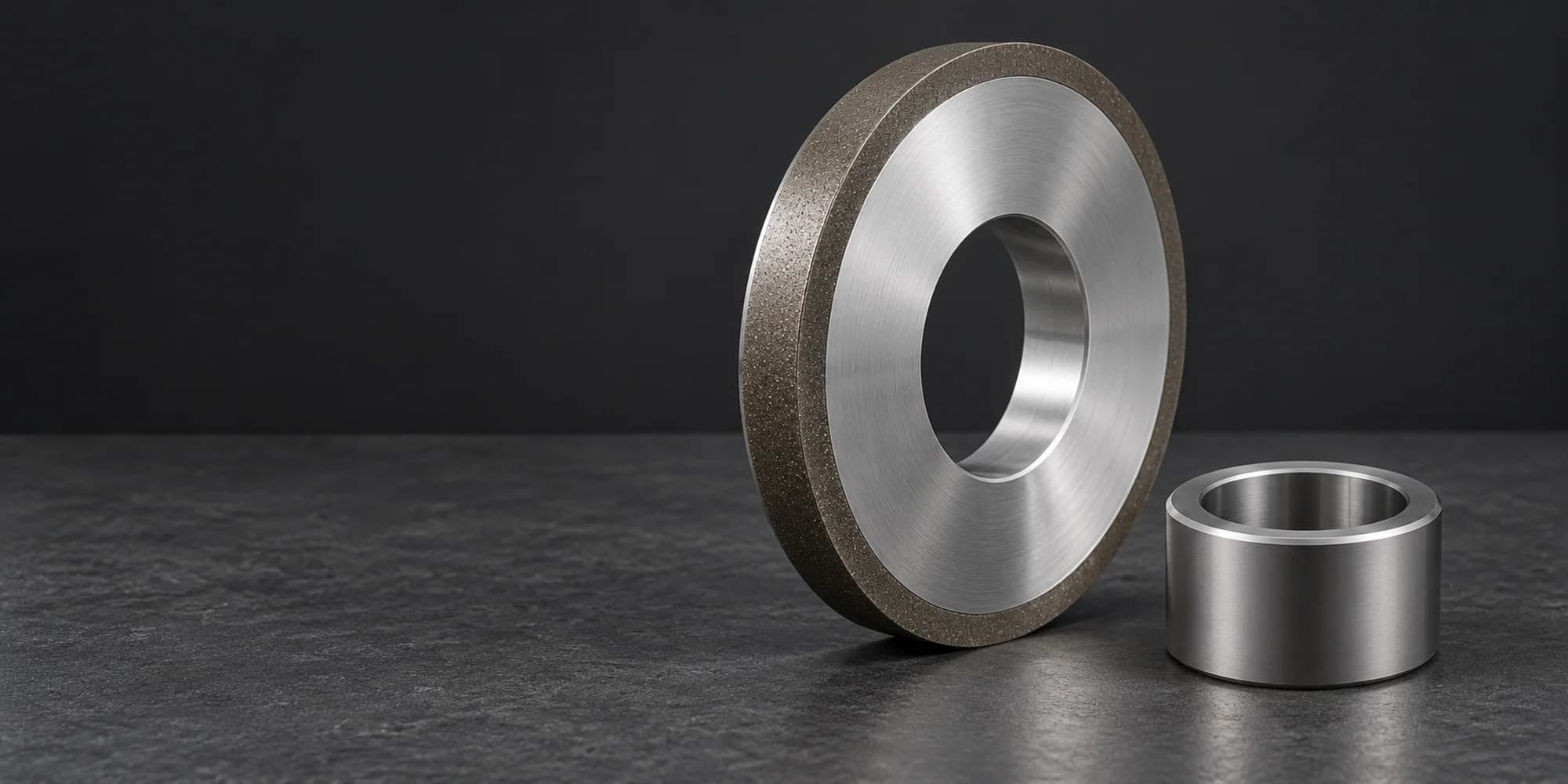
Diamond grinding wheel and a generic carbide wear ring on an inspection bench

Grinding Wheel Knowledge Base

Diamond Grinding Wheels for Tungsten Carbide Wear Parts: Bond Selection, Edge Chipping & Surface Finish

Diamond grinding wheel and a generic carbide wear ring on an inspection bench

A carbide wear ring meets its diameter and roughness requirements, but small chips keep appearing along a critical edge. A finer diamond wheel might help, but grit size is only one part of the problem: a wheel can produce an acceptable finish on a flat area while damaging an unsupported edge, or hold its profile while requiring a dressing method the machine cannot perform. For solid WC-Co wear parts, selection starts with the material, contact geometry and acceptance requirements, not a grit number taken from another application.

The material at the wheel decides which diamond specification is worth evaluating.
For solid WC-Co, diamond is the starting family, not the complete specification.
A passing Ra measurement does not prove the edge is intact.
A controlled trial needs separate criteria for surface, edge and geometry.

AI-generated concept illustration. Not a factory photograph, real product record or customer part. Wheel and part appearance is illustrative and does not define bond, grit or edge condition.

Overview

Start with the material system, not the grit number

The useful first question is not which diamond wheel to buy, but what the wheel is actually touching. A drawing that says tungsten carbide may describe a solid WC-Co wear part, a carbide-based coating on steel, or a steel substrate before coating. Each presents a different grinding interface, a different failure mode and a different inspection requirement.

This article focuses on solid cemented-carbide wear components, particularly precision parts where edge integrity, geometry and surface finish must be controlled together. It separates the material system, the diamond/CBN boundary, the bond evaluation and the edge acceptance decision before any wheel is selected.

The short version

  • Solid WC-Co, a carbide coating on steel and an uncoated steel substrate are different grinding systems. Confirm which one is at the wheel before selecting a diamond specification.
  • Diamond is the starting abrasive family for solid WC-Co, but the bond and working layer decide how the wheel behaves at an edge and how it holds a profile.
  • Edge chipping is a separate acceptance condition from surface roughness. Inspect where and when the damage occurs before changing grit size.
  • Qualify a candidate wheel against separate criteria for the primary surface, the critical edges and the required geometry.

First confirm what the wheel is grinding

The term tungsten carbide is used for several different material systems. A solid WC-Co part, a carbide-based thermal-spray coating on steel and an uncoated steel substrate do not share one grinding answer.

Why the material system comes first

Cemented carbide (WC-Co) contains hard tungsten carbide particles held together by a metallic binder, commonly cobalt. Its grinding behavior depends on the particular grade, microstructure and component design. A broad material name is not enough to select a diamond wheel.

What a coating changes

A steel component carrying a tungsten-carbide-based thermal-spray coating is a different system. The coating thickness, adhesion to the substrate and risk of grinding through the layer introduce separate constraints. Grinding the underlying steel before a coating is applied is a third case.

What this article covers

This article focuses on solid cemented-carbide wear components, particularly precision parts where edge integrity, geometry and surface finish must be controlled together. If the material at the wheel is unconfirmed, the abrasive decision is not yet supported; request the drawing or material specification.

What the wheel is grinding

What the wheel is grinding
Material being groundFirst questionWhy it matters
Solid cemented carbide (WC-Co)What carbide grade and binder system are specified?Material characteristics affect the grinding response
Tungsten-carbide-based coatingWhat is the coating process and remaining thickness?The coating and substrate form a different grinding system
Steel substrateWhat steel grade and heat-treatment condition are present?A carbide-wheel recommendation should not be transferred automatically
Unconfirmed materialCan the drawing or material specification be supplied?The abrasive decision is not yet supported

Solid cemented carbide (WC-Co)

First question

What carbide grade and binder system are specified?

Why it matters

Material characteristics affect the grinding response

Tungsten-carbide-based coating

First question

What is the coating process and remaining thickness?

Why it matters

The coating and substrate form a different grinding system

Steel substrate

First question

What steel grade and heat-treatment condition are present?

Why it matters

A carbide-wheel recommendation should not be transferred automatically

Unconfirmed material

First question

Can the drawing or material specification be supplied?

Why it matters

The abrasive decision is not yet supported

Solid WC-Co and a coated steel part are different grinding systems

The material at the wheel decides which questions come first. A solid carbide section and a carbide-based coating on steel do not present the same grinding interface.

Conceptual cross-section · not to scale

Solid WC-Co

  • WC grain
  • Co binder

WC grains are distributed through a metallic binder. The wheel grinds the whole section.

Grinding the bulk material

Carbide-based coating on steel

  • Coating layer
  • Adhesion interface
  • Steel substrate

A distinct thermal-spray coating sits on steel. Grinding must respect the coating, its adhesion interface and the specified remaining thickness.

Grinding the coating, not the bulk

Conceptual comparison. A solid WC-Co part and a carbide-coated steel part differ in material structure, coating thickness and inspection constraints.

Why diamond is a useful starting abrasive for cemented carbide

Diamond is widely used for grinding hard carbide materials because of its high hardness and wear resistance. That makes it a logical abrasive family to evaluate for many WC-Co applications. It does not establish the complete wheel specification.

What the starting family still needs

A diamond wheel still needs an appropriate bond system, abrasive characteristics, working-layer design and operating conditions. Diamond's hardness alone does not define the result.

The same grade can see different contact conditions

A broad face requires stable material removal over a large contact area. A narrow groove places different demands on the active abrasive profile. A thin edge may chip under grinding conditions that produce an acceptable finish elsewhere. A formed surface may require the wheel profile to remain within tight geometric limits. The wheel must be evaluated against the feature that determines whether the part is accepted.

The boundary with CBN

CBN is commonly evaluated for hardened ferrous materials, while diamond is generally the more relevant starting family for cemented carbide. A successful CBN specification for steel should not be reused on WC-Co solely because both materials are hard. The reverse transfer should be avoided as well: a diamond specification selected for WC-Co is not a steel-grinding specification.

Resin, vitrified, metal and electroplated diamond wheels

Bond selection changes how a diamond wheel retains abrasive grains, behaves under load and maintains its working profile. The matrix sets out what each construction is worth evaluating against.

A resin bond can meet finish and still wear quickly

A resin wheel that meets a finish requirement may wear too quickly for a demanding profile. Check actual form retention, wear, heat and achievable finish before selecting it.

A metal bond can hold form and still be hard to condition

A metal-bond wheel may hold a feature well but be difficult to condition on the available equipment. Determine how it will be trued, dressed or restored.

Electroplated is a single-layer construction

An electroplated profile wheel should not be treated as if it has the same renewable abrasive layer as a conventional multilayer resin-bond wheel. Account for its abrasive-layer construction and replacement strategy.

Start from the working shape and the machine

Before choosing a bond, establish the required working shape and how the grinding machine will maintain it. A wheel that cannot be conditioned on the available equipment is not a practical choice.

Bond selection is a set of evaluation directions

The four constructions answer different needs at the edge, the profile and the conditioning stage. None is automatically best for every carbide wear part.

Evaluation directions, not interchangeable specifications

ConstructionEdge and finishProfile retentionConditioningWhat to verify

Resin bond

Diamond grains distributed through a resin-bond working layer.

Edge and finish

Evaluate for finish and contact compliance

Profile retention

Verify form retention under load

Conditioning

Conditionable; check wear rate

What to verify

Actual finish, wear and form

Vitrified bond

Diamond grains distributed through a vitrified-bond working layer.

Edge and finish

Evaluate where a dressable face is needed

Profile retention

Verify profile control after dressing

Conditioning

Requires a suitable dressing system

What to verify

Wheel design and dressing capability

Metal bond

Diamond grains distributed through a multilayer metal-bond working layer.

Edge and finish

Evaluate for strong grain retention

Profile retention

Verify form holding and conditioning

Conditioning

May need special truing or dressing

What to verify

Restoration method on the machine

Electroplated

One exposed diamond-grain layer held by electrodeposited metal on a core; not a renewable multilayer rim.

Edge and finish

Evaluate for single-layer profile work

Profile retention

Profile is fixed by the plated layer

Conditioning

Non-dressable; plan replacement

What to verify

Layer construction and replacement strategy

Construction sketches are conceptual and not to scale. Diamonds indicate abrasive grains; the base band indicates the core. Grain count, spacing and layer depth are not specifications.

Conceptual matrix. Each bond family is paired with the evidence to verify before selection.

Why carbide edges chip even when the surface finish looks acceptable

A roughness measurement taken across the main surface does not necessarily reveal what happened at an edge. In precision wear components, edge integrity can be a separate acceptance requirement.

The wheel reaches an unsupported edge

As the grinding contact approaches an edge, the local support and material-removal conditions change. A pass that is stable across the main surface may produce chipping at the exit or along a thin feature. Record exactly where the chips occur: an entry edge, exit edge, groove corner and unsupported lip do not necessarily fail for the same reason.

The abrasive surface is no longer cutting effectively

A worn, loaded or improperly conditioned wheel can alter grinding forces and contact behavior. Check the condition of the abrasive layer before assuming the grit is too coarse. Where the construction allows it, inspect the results before and after an appropriate truing or dressing operation. For single-layer constructions, use the manufacturer's recommended inspection and replacement procedure instead.

Too much material is removed in a critical region

Local stock variation or an aggressive infeed can change contact severity. Compare the incoming geometry with the final drawing. If excess material is concentrated near an edge, a nominally consistent grinding cycle may not produce consistent results.

The part or fixture is unstable

A small carbide component may be sensitive to clamping, support location or vibration. Check the fixture and machine condition, particularly where the damaged feature is thin, interrupted or difficult to support.

The damage existed before grinding

Inspect an incoming sample before the operation. If the feature has already been damaged during previous handling or processing, a finished-part inspection alone cannot establish when the defect occurred. Practical rule: inspect the location, form and timing of the damage before changing the wheel specification.

Where the edge is loaded, and when the damage occurred

Chip location and timing are evidence. The same chip can come from an unsupported edge, an ineffective abrasive surface, excess local stock, an unstable fixture or pre-existing damage.

Local 2D section · conceptual · not to scale

Contact at the edge

  • Diamond-bearing peripheral rim
  • WC-Co workpiece
Local contact detail

Typical edge-chipping location

A
Entry edge
B
Exit edge
C
Unsupported lip
D
Support
E
Local stock
F
Relative traverse toward exit

The outer working rim is tangent to the surface; the core is clear of the workpiece. The arrow shows relative traverse, not wheel rotation or an infeed setting. The stock patch illustrates allowance only.

When did the damage occur?

  1. Incoming inspection

  2. Grinding

  3. Finished-part inspection

Damage already present at incoming inspection cannot be attributed to this grinding step alone.

Possible factors to investigate — not a single-cause diagnosis

  • Unsupported edge
  • Ineffective abrasive surface
  • Excess local stock
  • Unstable fixture
  • Pre-existing damage
Conceptual diagram. The contact view is a local cross-section; the timeline shows why incoming inspection matters before a chip is attributed to grinding.

Grit size and finish: finer is not the whole answer

A finer abrasive size may be considered when the target surface finish becomes more demanding. But a finer grit does not by itself eliminate chipping, improve geometry or lower grinding temperature. The result still depends on grain exposure, stock removal, contact area and edge geometry, bond behavior, coolant delivery, and machine rigidity.

Roughness and edge integrity are different acceptance conditions

A component can satisfy its Ra requirement and still fail because an edge is chipped or a profile has drifted outside tolerance. Conversely, a wheel may leave acceptable edges but fail the required surface finish.

Define separate acceptance criteria

For this reason, define separate acceptance criteria for the primary surface, the critical edges and the required geometry. A single Ra number does not cover the part.

Diagnose the grinding problem before replacing the wheel

Use the symptom to decide what evidence to collect. The table is a starting sequence, not a fault diagnosis based on appearance alone.

Separate a process change from a wheel change

A process change and a wheel specification change can create similar symptoms. The investigation should separate them before making a supplier or manufacturing-quality judgment.

What the evidence needs to show

Record the damage location, incoming condition, support, contact direction, infeed, wheel-face condition, and the timing of the damage. If the symptom follows a dressing tool, coolant change or workpiece lot instead of the wheel, the wheel may be the wrong place to look.

What the symptom can tell you

What the symptom can tell you
Observed problemInvestigate first
Edge chippingDamage location, incoming edge condition, support, contact direction, infeed and wheel-face condition
Surface finish deteriorates during productionAbrasive-layer condition, loading, coolant, dressing or replacement interval, and machine stability
Wheel loses profileBond and construction, abrasive-layer wear, contact geometry and process severity
Grinding forces or noise increaseAbrasive sharpness, material or stock change, mounting, coolant and machine condition
Dimensions driftWheel wear, fixture movement, thermal effects, compensation and measurement method
Results vary between replacement wheelsWheel identification and lot, conditioning method, incoming workpiece variation and controlled process comparison

Edge chipping

Investigate first

Damage location, incoming edge condition, support, contact direction, infeed and wheel-face condition

Surface finish deteriorates during production

Investigate first

Abrasive-layer condition, loading, coolant, dressing or replacement interval, and machine stability

Wheel loses profile

Investigate first

Bond and construction, abrasive-layer wear, contact geometry and process severity

Grinding forces or noise increase

Investigate first

Abrasive sharpness, material or stock change, mounting, coolant and machine condition

Dimensions drift

Investigate first

Wheel wear, fixture movement, thermal effects, compensation and measurement method

Results vary between replacement wheels

Investigate first

Wheel identification and lot, conditioning method, incoming workpiece variation and controlled process comparison

How to qualify a diamond wheel for a carbide wear part

A trial should answer whether a proposed wheel meets the required part quality under practical production conditions. Qualification has six steps; the three acceptance lanes are separate. If chipping, visible damage, unsafe operation or unacceptable dimensional results occur, stop the trial and follow the agreed inspection and corrective-action procedure.

Step 1 — Confirm the material and drawing

Record the carbide grade, binder system where known, component shape, critical edges, stock allowance and final inspection requirements.

Step 2 — Record the existing wheel and process

Include the complete wheel marking, abrasive-layer dimensions, bond system, machine, mounting, coolant, operating conditions and conditioning method.

Step 3 — Define what a successful result means

Agree on dimensional tolerance, form, surface roughness, edge condition, applicable surface-integrity inspection and part acceptance.

Step 4 — Test the candidate under documented conditions

Keep the comparison as consistent as practicable. Record any differences in material lot, setup or process.

Step 5 — Inspect the accepted parts and the wheel

Measure the required part features and examine the abrasive layer for wear or loss of profile. Do not rely only on a visual impression of surface polish.

Step 6 — Evaluate production cost only after quality is demonstrated

Compare wheel consumption, conditioning events, cycle time, accepted parts and rework where records are available. A longer wheel life cannot justify damaged carbide components.

A trial that tests quality before cost

Qualification has six steps and three acceptance lanes. Edge integrity is a gate, not a note added after the surface result.

  1. Confirm material and drawing

    Grade, binder, shape, critical edges, stock and inspection requirements.

  2. Record current wheel and process

    Marking, abrasive layer, bond, machine, coolant and conditioning.

  3. Define success

    Surface, edge, geometry and acceptance criteria.

  4. Run a documented trial

    Keep conditions consistent; record differences.

  5. Inspect parts and wheel

    Measure features; check wear and profile loss.

Geometry: profile and tolerance

Primary surface: Ra and finish

Critical edges: chips and edge integrity

  1. Review cost after quality

    Consumption, conditioning, cycle time and rework.

Conceptual trial flow. The five working steps precede three acceptance lanes, the stop gate and the final cost review.

What to send

Send the carbide part drawing and current diamond wheel details

For a non-standard carbide grinding application, a drawing and a clear description of the present process are usually more useful than a generic wheel catalogue. Youlin Abrasive manufactures customized grinding wheels and abrasive tools for precision industrial applications. With more than 20 years of grinding wheel manufacturing experience, we review non-standard wheel requirements against the supplied application conditions rather than assuming one fixed specification will fit every carbide component. Send the drawing, the current diamond wheel specification and the problem you want to solve; we can discuss the specification areas that deserve evaluation and the conditions for a controlled sample trial.

  • The actual carbide grade and material condition, if available

  • The component drawing, including critical edges, profiles and form tolerances

  • The current diamond wheel dimensions, shape, bore, bond and abrasive-layer details

  • The grinding machine, mounting arrangement and operating conditions

  • Wet or dry operation, coolant type and delivery conditions

  • Existing grinding and dressing or conditioning information

  • Required surface roughness, edge condition, edge-chipping acceptance criteria and inspection requirements

  • Photos of the part, current wheel and observed defects, if relevant

Need help reviewing a carbide wear-part application?

Send the carbide component drawing, current diamond wheel specification and the problem you want to solve. We can discuss the specification areas that deserve evaluation and the conditions for a controlled sample trial. Youlin Abrasive supplies grinding wheels and abrasive tools; we do not supply carbide components, workpieces, machines or machining services.

Send Grinding Details →

FAQ

Questions about diamond wheels for carbide wear parts

Short answers for production and purchasing teams reviewing a solid WC-Co wear part.

Are diamond grinding wheels suitable for WC-Co cemented carbide?

Diamond is an established abrasive family for many cemented-carbide grinding applications. The correct wheel construction and specification still depend on the carbide grade, operation, geometry, machine and acceptance requirements.

Should I choose a finer diamond grit to prevent edge chipping?

Not from the symptom alone. First examine where the damage occurs, the wheel-face condition, local stock allowance and workpiece support. Grit size can then be evaluated alongside the bond and process.

Which is better for carbide: resin-bond or metal-bond diamond?

Neither can be selected from the material name alone. Resin and metal bonds offer different behavior in grain retention, compliance, wear and profile maintenance. The required finish, form, dressing capability and operating conditions determine which designs are worth testing.

Can the same diamond wheel be used for solid carbide and carbide-coated steel?

Do not assume so. A solid cemented-carbide component and a coated steel part have different material structures and inspection constraints. Verify the actual coating or material before transferring a wheel specification.