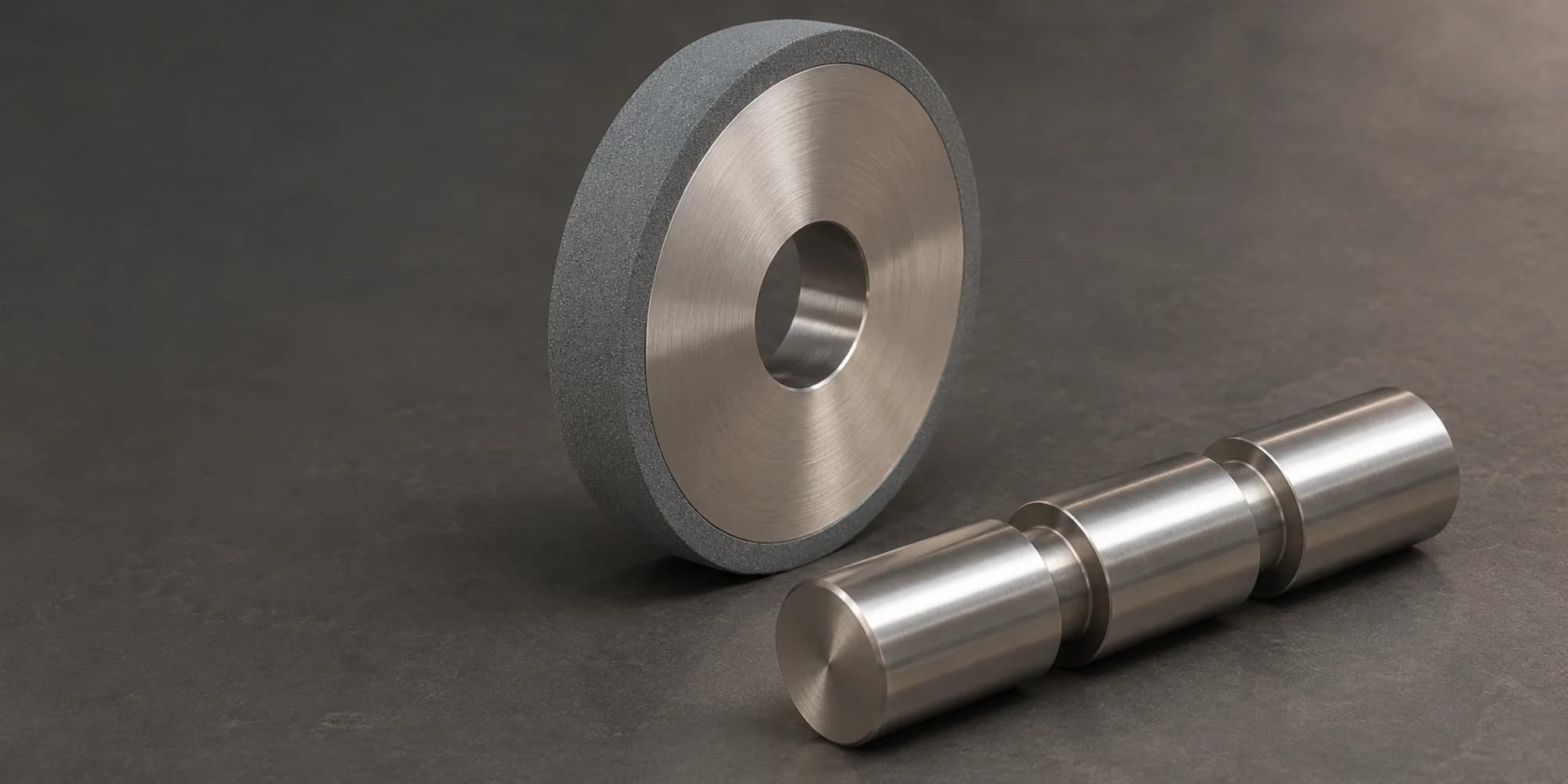
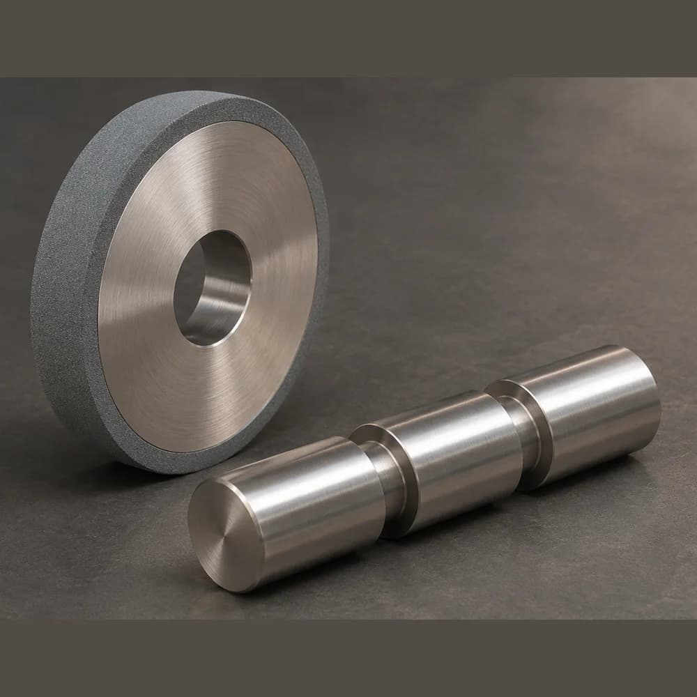
Bonded grinding wheel and a generic hydraulic spool on an inspection bench

Grinding Wheel Knowledge Base

Grinding Wheels for Hydraulic Valve Spool OD Grinding: Roundness, Land Edges & Surface Finish

Bonded grinding wheel and a generic hydraulic spool on an inspection bench

A spool can pass its diameter check and still fail at the valve test. The land may be oval rather than round, the functional edge that meters flow may carry a burr, or the finish may meet Ra while the texture and edge condition do not satisfy the drawing. This guide covers the wheel and process review those features require: how the drawing, the OD operation, the ground layer and the acceptance method change the wheel recommendation, and how to qualify a candidate without treating one grit number as the answer.

Read the spool drawing before the wheel: land, groove, shoulder and functional edge are different contacts.
Diameter, roundness, land-edge condition and surface finish are separate acceptance conditions.
Abrasive family follows the actual ground layer; CBN is conditional and diamond is not for steel.
A part-edge burr is not the same as a wheel-corner chip.
Qualify the wheel on the actual machine with one variable changed at a time.

Conceptual AI-generated illustration. Not an actual YOULIN product, customer workpiece or verified grinding setup. AI-generated concept illustration. Not a factory photograph, real product record or customer part. Wheel and spool appearance is illustrative and does not define bond, grit, land width, edge condition or measured result.

Overview

Start with the spool features and the drawing

A hydraulic spool is not a plain shaft with a single diameter. It may carry lands separated by grooves, shoulders at the ends and functional edges where a land meets a groove or port. The wheel can meet a continuous cylindrical land, an interrupted groove, a shoulder face and an edge that controls flow — often in the same cycle.

The drawing decides which of those surfaces are ground, which datum locates them and how they are inspected. A wheel recommendation without that information is a guess. This article keeps the scope on the external cylindrical features of the spool. Valve plates, valve bodies and sleeves are different workpieces and different grinding contacts.

The short version

  • Read the drawing before the wheel: identify which features are ground, which datum locates them and how roundness, land width, edge condition and finish are inspected.
  • Land OD, groove, shoulder and functional edge are different grinding contacts. One wheel or one operation may not cover all of them.
  • Diameter, roundness, edge integrity and surface finish are separate acceptance conditions. A micrometer reading and an Ra value do not prove a spool will function.
  • Abrasive family follows the actual ground layer: uncoated steel, a hardened case, a stainless grade or a coating are different decisions.
  • CBN is a conditional option for hardened ferrous spools, not an automatic choice. Conventional aluminum oxide remains valid. Diamond is not for steel.
  • Roundness errors can come from the workholding or machine. A burr at the functional edge is not the same as chipping at the wheel corner.
  • Qualify a candidate on the actual machine against separate criteria for size, roundness, edge and finish. Change one variable at a time.

The drawing defines four different features

A spool may carry lands separated by grooves, with shoulders at the ends and functional edges where a land meets a groove or port. The drawing decides which of those surfaces are ground and how they are inspected.

Land, groove, shoulder and functional edge are not interchangeable

The land is the cylindrical working band that fits the valve body bore; its outside diameter, width and position matter. The groove separates lands or routes flow; its root, flanks and corner may be machined, ground or left as clearance. The shoulder is a diameter change at the end of a land. The functional edge is the edge that opens or closes a flow path, often at a land/groove or land/port transition; it may carry a chamfer or radius.

Not every feature is ground

A groove root may be rough-machined, a shoulder may be left with a defined undercut, and an edge form may be produced before grinding. The review should identify which surfaces the wheel actually owns. One wheel does not have to cover every feature; a shop may rough the land with one wheel, finish it with another and generate a shoulder or groove form with a dressed wheel or a separate operation.

The drawing defines the datum and the inspection positions

A diameter at one axial position does not describe a land that tapers or a spool that bends between supports. Ask which surface locates the part during grinding and which surface locates it during inspection; they are not always the same. Mark the axial positions and the method used for roundness, land width and edge inspection.

Valve plate, valve body and valve sleeve are different parts

A valve plate is a flat pump component, not a cylindrical spool. Grinding the bore of a valve body or sleeve is also a different contact from grinding the spool OD. This article stays with the spool's external cylindrical features; plate flatness and bore geometry need their own reviews.

A coating changes the material decision

If the spool carries a coating, the coating is the surface being ground. Hard chrome, electroless nickel and other deposits do not share one wheel answer. Identify the coating family, thickness and remaining allowance before transferring a steel specification; the coating-specific review belongs with the hard-chrome guide.

Conceptual section, not to scale

Conceptual cross-section of a hydraulic spool showing land, groove, shoulder and functional edgeConceptual section, not to scale123456
  1. 1Land
  2. 2Groove
  3. 3Shoulder
  4. 4Functional edge
  5. 5Land width
  6. 6Groove width
Rotation axisMay be ground depending on drawing

Edge detail is an illustrative option only. The drawing defines a sharp edge, chamfer, radius or edge break; no value is implied.

The drawing and inspection method define acceptance.

Four features that change the wheel and process review. Dashed outlines show surfaces that may be ground; they are not all ground on every spool.

The operation matters as much as the part name

“Valve spool OD grinding” can describe several machine setups. The wheel sees a different contact in each, and the same spool may need more than one operation.

Traverse grinding

The wheel is narrower than the ground length and moves along the land. Wheel width, traverse rate and overlap affect the pattern and the wear across the face. A land beside a groove has an interrupted contact at each end. The wheel width and the traverse direction should be recorded, not assumed from the part name.

Plunge grinding

The wheel width is matched to the land or a defined section and fed radially. The contact area is larger, the normal force is higher, and the wheel corner and width become part of the geometry. Plunge grinding is often used where the land is narrow or where a shoulder and land are ground in one cycle; the actual setup must come from the drawing and machine.

Shoulder work and wheel-face limits

Shoulder/form work needs a wheel whose working face and machine are approved for that contact. A wheel designed for the job can carry a dressed profile for a shoulder, radius, chamfer or groove form; a relieved side or dressed corner can instead provide clearance to the shoulder. The side of a general peripheral wheel is not an approved grinding face. Limited side contact is a specific application, not a default operation. Confirm the wheel marking, allowed working face and clearance before the trial.

Centerless grinding

A centerless operation supports the workpiece on a regulating wheel and a work rest blade. It can be efficient for a plain cylindrical section, but it does not inherently preserve axial features or a relationship to a shoulder or functional edge. It should not be treated as a direct substitute when lands, grooves and edge positions are located from a face datum.

Workholding and one wheel may not cover every feature

Between-centers grinding, a chuck, a steady rest and tailstock pressure can each leave a roundness signature. A slender spool may deflect under grinding force. If the roundness problem changes when the support changes, the wheel is not the only variable. Identify which wheel owns which surface instead of asking one specification to satisfy every contact.

Wheel rotation · separate end view
Workpiece rotation · separate end view

End views identify two separate rotations; arrow directions are illustrative, not a selected speed ratio or machine setting. Straight arrows show relative axial motion or radial infeed.

Traverse

A wheel narrower than the land moves along it; contact is interrupted at the groove.

Conceptual, not to scale · Axial section · illustrative local contact

Conceptual diagram of traverse and plunge OD grinding contacts, plus a shoulder-clearance check on a hydraulic spoolConceptual, not to scale1234
  1. 1Wheel width
  2. 2Land length
  3. 3Interrupted contact
  4. 4Traverse direction

Plunge

A wheel width matched to the land feeds radially; the corner meets the functional edge.

Conceptual, not to scale · Axial section · illustrative local contact

Conceptual diagram of traverse and plunge OD grinding contacts, plus a shoulder-clearance check on a hydraulic spoolConceptual, not to scale1234
  1. 1Radial infeed
  2. 2Wheel corner
  3. 3Wheel width vs land width
  4. 4Clearance

Shoulder clearance & wheel-face review

The wheel's peripheral working face grinds the land OD. The side relief and dressed corner must clear the shoulder; check which wheel face is approved for contact.

Conceptual, not to scale · Axial section · illustrative local contact

Conceptual diagram of traverse and plunge OD grinding contacts, plus a shoulder-clearance check on a hydraulic spoolConceptual, not to scale123456
  1. 1Wheel peripheral working face
  2. 2Land
  3. 3Groove
  4. 4Shoulder
  5. 5Wheel side relief / dressed corner
  6. 6Clearance to shoulder — verify no side contact
Illustrative contact zone

Edge detail is an illustrative option only. The drawing defines a sharp edge, chamfer, radius or edge break; no value is implied.

Do not treat the side of a peripheral wheel as an approved grinding face. Profile/form work requires a wheel designed for that working face; limited side contact requires specific wheel and machine approval. A general straight wheel is not approved for side grinding without that specific approval.

Traverse and plunge are alternative contact concepts; the shoulder panel is a clearance check, not a third required operation for every spool. Supports, guards, flanges and coolant are omitted; this is not an operating instruction.

Centerless grinding is not a universal substitute when axial features and edge positions are located from a face datum.

Traverse and plunge change the contact width and the role of the wheel corner. The third panel checks shoulder clearance and which wheel face is allowed to contact.

Four acceptance conditions, not one number

A spool drawing can carry several requirements that are measured in different ways. They should remain separate during wheel selection and during a trial.

Diameter is not roundness

A part can measure within size at every point a micrometer touches and still be oval. A two-point measurement can miss a three-lobed form depending on orientation. If the drawing calls for roundness or cylindricity, use the inspection method that actually evaluates that requirement rather than substituting a diameter reading.

Roundness and cylindricity need their own method

Record the roundness trace, the axial positions, the datum and the filter. A trace at one position may miss a taper or a bend along the land. The customer's drawing and inspection procedure define the requirement, including the tolerance and instrument.

Land width and edge condition are not in a roughness result

A land can be the correct width and still carry a burr at the functional edge. Edge condition needs its own inspection, often under magnification. Record the drawing dimensions, the edge specification and whether the edge is sharp, chamfered, radiused or edge-broken.

Surface finish is one lane, not the definition of quality

Ra is a two-dimensional parameter with a cutoff and a direction. The same Ra can describe different textures, and a smoother surface is not automatically a better spool. Roundness, land width, edge integrity, clearance and surface texture all contribute to how the spool behaves.

Agree the acceptance plan before comparing wheels

List diameter, roundness/cylindricity, land width and position, functional-edge condition and surface finish, each with its measurement method. Without that plan, a wheel change can improve one number while damaging the feature that decides whether the valve works.

Four acceptance lanes

Four acceptance lanes
What it controls
Insufficient check
Evidence to record
First check

Diameter / size

What it controlsFit at the measured section
Insufficient checkOne micrometer reading at one plane
Evidence to recordAxial positions, instrument, temperature
First checkConfirm measurement positions

Roundness / cylindricity

What it controlsRadial deviation around and along the land
Insufficient checkDiameter alone or a two-point check
Evidence to recordRoundness trace, axial positions, datum, filter
First checkCheck centers and workholding

Land width, position and functional edge

What it controlsFunctional geometry and metering edge
Insufficient checkLow-magnification visual check
Evidence to recordDrawing dimensions, magnified edge photo, burr result
First checkInspect wheel corner and part edge

Surface finish / texture

What it controlsRoughness, waviness, lay and surface condition
Insufficient checkOne Ra value without cutoff or direction
Evidence to recordParameter, cutoff, instrument, location, direction
First checkCheck wheel face and dressing

Wheel specification follows the ground layer

The first specification question is not “which grit?” It is “what material is the wheel cutting, and in what condition?”

Identify the ground layer first

A spool drawing may specify a through-hardened alloy steel, a case-hardened steel, a stainless grade or another material. The heat-treatment condition and the depth of the hardened layer change the grinding behavior. If the stock removal crosses from a hard case into a softer core, the wheel is no longer cutting one material.

Uncoated steel: conventional aluminum oxide or conditional CBN

For a hardened ferrous spool, CBN may be worth evaluating because it is harder than aluminum oxide and can hold a land width or a dressed corner well in the right machine and dressing system. It is not automatic. A conventional aluminum oxide wheel may remain the better choice for a softer or medium-hardness spool, a low-volume batch, or a machine that cannot support the CBN dressing and coolant requirements.

Coated spools need coating identification

If the spool carries a coating, identify the coating family, thickness and remaining allowance. A hard chrome layer, a nickel-based deposit and a carbide coating do not share one abrasive recommendation. Do not transfer a substrate specification to the coating, or a coating specification back to the substrate.

Grit, grade, structure and bond are not independent dials

Grit size affects the potential finish and chip space, but a finer grit does not by itself fix a roundness error or an edge burr. Wheel grade describes how firmly the bond holds the grain in a conventional wheel; a harder grade does not automatically improve roundness. Structure affects chip clearance and coolant access. Bond must suit the wheel construction and the dressing method.

Wheel shape, width and corner must fit the drawing

A straight wheel is a common starting shape for a land OD, but a wheel wider than the land can rub an adjacent shoulder or groove, and a wheel that is too narrow increases the number of passes and the opportunity for a step or taper. Where a shoulder needs clearance, a relieved or recessed wheel may be needed. A specified corner radius or chamfer must be dressed to form and maintained by the dressing system.

Roundness: separate the wheel from the workholding

A roundness problem is often described as a wheel problem, but the wheel is one possible source among several.

The shape of the error is evidence

Ovality, lobing, a barrel or hourglass profile and random variation do not all point to the same cause. A trace taken at one axial position may miss a taper or a bend along the land. Record where the trace was taken and how the part was supported.

Machine and workholding signatures

Center misalignment or incorrect center depth tends to show once per revolution. Chuck jaws or a worn collet can distort the part at the clamping section; a steady rest set too hard or in the wrong position can press a lobed form into the land; and tailstock pressure can bend a slender spool. Spindle error, wheel imbalance, a poorly seated flange or drive vibration add a separate chatter pattern. Read the signature before changing the wheel.

Wheel and process evidence

Wheel wear across the land changes the effective contact and can leave a taper or a stepped trace. Grade and structure affect how the face holds its form and clears chips; loading or glazing raises heat and normal force; depth of cut, feed and spark-out determine how much elastic deflection is recovered before the wheel leaves the cut; and coolant delivery affects thermal distortion. Treat these as evidence of what the wheel is doing, not settings to change all at once.

Build a baseline before changing the wheel

Use the same material lot, machine, workholding and inspection method. If roundness changes when the steady rest is moved or the centers are cleaned, the wheel is not the first variable to change. If the error follows the wheel change, the wheel-face condition and dressing become the next evidence.

A harder wheel is not a roundness fix

A harder grade can reduce self-sharpening and increase heat, which may worsen the result. Change the wheel only when the evidence points to the wheel rather than the support, the machine or the cycle.

Land edges: a burr is not the same as wheel chipping

The functional edge is where the spool controls flow. A small burr or a rounded edge can change leakage or response, even when the land diameter and Ra are acceptable.

A burr at the workpiece edge

Metal is pushed or smeared at the edge rather than cleanly cut. It can follow a wheel exit, insufficient support, a dull wheel, excessive feed, a worn wheel corner or a coolant problem. The burr may be consistent along one side of the land or appear only at the exit end.

Chipping at the wheel corner

The abrasive layer at the wheel corner fractures or breaks away. The wheel then cuts a different edge, and the workpiece may show a scratch, a step or an edge break. The evidence is on the wheel as well as the part: inspect the wheel corner under magnification and compare it with the part edge.

They can look similar but the correction is different

A wheel-corner chip may require a different bond, grade, corner preparation or dressing approach. A workpiece burr may require support, exit conditions, feed or wheel-face attention. Changing the grit alone may address neither.

Inspect both sides and the timing

Record whether the damage repeats at the same axial position, appears after a wheel change or dressing, or varies with the material lot. A repeatable scratch or step points toward the wheel corner; a burr that follows the exit or support points toward the part-edge condition.

The drawing defines the edge

Chamfer, radius, edge break or sharp condition is a drawing requirement. Do not add or remove an edge break to make the part look better. If the edge specification is missing, ask for it before selecting a wheel corner.

Burr or wheel-corner chip?

Part-edge burr

Where to look
Workpiece edge, especially the exit side
What it looks like
Metal pushed or smeared at the edge
What else to check
Support, feed, exit condition, wheel face
First evidence
Magnified edge photo and timing vs cycle

Wheel-corner chip

Where to look
Abrasive layer at the wheel corner
What it looks like
Fractured or missing abrasive at the corner
What else to check
Repeatable scratch/step, wheel change or dressing
First evidence
Wheel-corner photo and part-edge location map

Appearance and first checks guide evidence collection; they do not establish a unique fault cause or acceptance limit.

These are different failure modes; changing grit alone may address neither.

Four separate acceptance lanes, and the evidence that separates a part burr from a wheel-corner chip.

Surface finish: Ra is one number, not the acceptance decision

Surface finish is usually reported as Ra. Ra is useful, but it is a two-dimensional parameter with a cutoff and a measurement direction.

What Ra does not describe

Ra does not describe waviness, lead, a smeared surface, a burn, a scratch or an edge burr. A land can meet Ra and still show a directional texture that affects sealing or sliding.

A slightly higher Ra can still be the better functional result

A slightly higher Ra with a uniform, non-smeared texture and a clean functional edge may be more useful than a lower Ra with a damaged edge or a wavy land. That is a functional judgment for the drawing and the valve test, not a universal rule.

Where finish problems come from

Check wheel grit, grade, bond or structure; wheel-face loading, glazing or dull grain; dressing condition and wheel corner; coolant delivery, filtration or concentration; depth of cut, feed, spark-out and machine vibration; and roundness or workholding error that changes the effective contact.

Do not chase Ra with a finer grit first

A finer grit can reduce the apparent roughness while making the wheel more prone to loading or heat, and it does not correct a lobed land or a burred edge. Check the wheel face, dressing and roundness before changing grit size.

Record the measurement method

Record the parameter, cutoff, instrument and measurement location. Compare results taken the same way. A change in filter or direction can look like a process improvement when it is only a different measurement.

Dressing and coolant keep the land and edge stable

Dressing restores the wheel face, the wheel corner and the effective contact. Coolant must reach the contact at the land, the shoulder and the groove.

Dressing is not only a cleaning step

On a spool, a dressing change can affect land width, edge condition and roundness at the same time. Record the dressing tool, method, depth, lead and interval, and what changed after dressing.

Read the dressing response

A wheel that improves immediately after dressing and then fades may have a grain-retention, wheel-face or dressing-depth issue rather than a wrong grit. A wheel corner that breaks down quickly may need a different bond, grade or corner preparation.

CBN dressing differs by bond

A vitrified CBN wheel, a resin-bond wheel and a metal-bond wheel are not conditioned in the same way. Do not copy a conventional-wheel dressing setting onto a CBN wheel without confirming the wheel construction and the machine capability.

Coolant has to reach the difficult contact

A nozzle that floods the outside of the wheel but misses a narrow land or a shoulder corner leaves the most difficult contact undercooled. Check nozzle position, flow, filtration and contamination. The fluid used by the finished hydraulic system is not the grinding coolant specification.

Mounting, balance and the marked speed limit

A wheel that is not mounted correctly or a flange that does not seat properly can produce a roundness or chatter signature that no grit change will fix. Confirm the wheel marking and the machine speed limit before running. The marked maximum operating speed and the machine documentation remain the limit.

Qualify the wheel on the actual spool

A useful trial compares one candidate wheel against the current process without changing several variables at once. The acceptance criteria should be agreed before the first part is ground.

Record the baseline

Record the current wheel marking, machine, material lot, heat treatment or coating, workholding, dressing, coolant and current acceptance results. Keep a first-part and a last-part record where possible.

Define the separate acceptance lanes

State the method for diameter, roundness/cylindricity, land width and position, functional-edge condition and surface finish. Do not let one result stand in for another.

Change one variable

Wheel specification, dressing and coolant should not all move at once. If the wheel is the candidate, keep the process as stable as the production requirement allows so the result can be interpreted.

Run enough parts and inspect the edge

A first-part result can flatter a wheel that changes after wear or dressing. Inspect the wheel corner and the part edge at the same intervals, not only the land surface.

Stop on damage and compare cost after acceptance

If the part shows a crack, burn, edge damage or an unacceptable geometry change, stop and inspect before continuing. Wheel life and cycle time are useful only when the accepted part result is maintained.

Before You Inquire

What to send for a spool OD wheel review

A wheel recommendation is only as specific as the application information behind it. Send the drawing, the current wheel and the measured results; mark unknown items rather than estimating them. Youlin supplies grinding wheels and abrasive solutions only; the spool design and the valve acceptance decision remain with the customer.

The spool drawing with land, groove, shoulder and functional-edge geometry, datums and the surfaces to be ground
Material grade, heat treatment, hardness and case depth where applicable
Coating family, thickness and remaining allowance if the spool is coated
The operation: traverse, plunge, shoulder/form or centerless, with machine model and workholding
The current wheel marking, dimensions, shape and mounting arrangement
The dressing method, tool condition and interval
The grinding coolant, delivery method and filtration
Current results for diameter, roundness, land width, edge condition and surface finish, with the measurement method used
Magnified photos of the wheel corner and part edge, plus a photo of the setup where possible
Batch size and whether the problem appears on the first part, after dressing or later in the run

Send these details through the inquiry form, or contact us on WhatsApp for a preliminary recommendation.

Send Grinding Details →

FAQ

Frequently asked questions

Quick answers to common buyer questions before sending an inquiry.

Can one wheel grind the land, groove and shoulder in one setup?

Not necessarily. The land OD, groove and shoulder present different contacts and may need different wheel shapes, widths or operations. A single setup can work when the wheel geometry and the drawing allow it, but the review should identify which wheel owns which surface rather than assuming one specification fits all.

Is CBN required for hydraulic valve spool OD grinding?

No. CBN may be worth evaluating for a hardened ferrous spool where land width, edge retention and wheel life matter, but it depends on the machine, dressing system, coolant and cost per accepted part. A conventional aluminum oxide wheel can remain suitable for a softer or medium-hardness spool or a process that is already stable.

Why is the spool out of round when the diameter is within tolerance?

Diameter and roundness are different measurements. A two-point micrometer check can miss a lobed or oval land, and the error may come from centers, workholding, steady-rest pressure, wheel balance or the grinding cycle. Check the measurement method and the support before changing the wheel grade.

How do I tell a workpiece burr from wheel-corner chipping?

Inspect both the part edge and the wheel corner under magnification. A wheel-corner chip is visible on the abrasive layer and often produces a repeatable scratch or edge break; a workpiece burr is metal deformation at the edge and may follow the exit, support or wheel-face condition. The timing relative to a wheel change or dressing is also evidence.

Does a better Ra guarantee the spool will function?

No. Ra is one surface parameter. Roundness, land width, edge condition, surface texture, clearance and the valve test all affect function. A lower Ra with a burred edge or a lobed land is not a better spool.

Can a diamond wheel be used on a valve spool?

Not on a steel spool. Diamond is generally reserved for cemented carbide, ceramics, glass and other hard, brittle non-ferrous materials. A coated spool needs the coating family identified first; a steel or hard-chrome surface is not a diamond application by default.