Grinding Wheels for Hydraulic Component Grinding: What Buyers Should Review

Grinding Wheel Knowledge Base

Grinding Wheels for Hydraulic Component Grinding: What Buyers Should Review

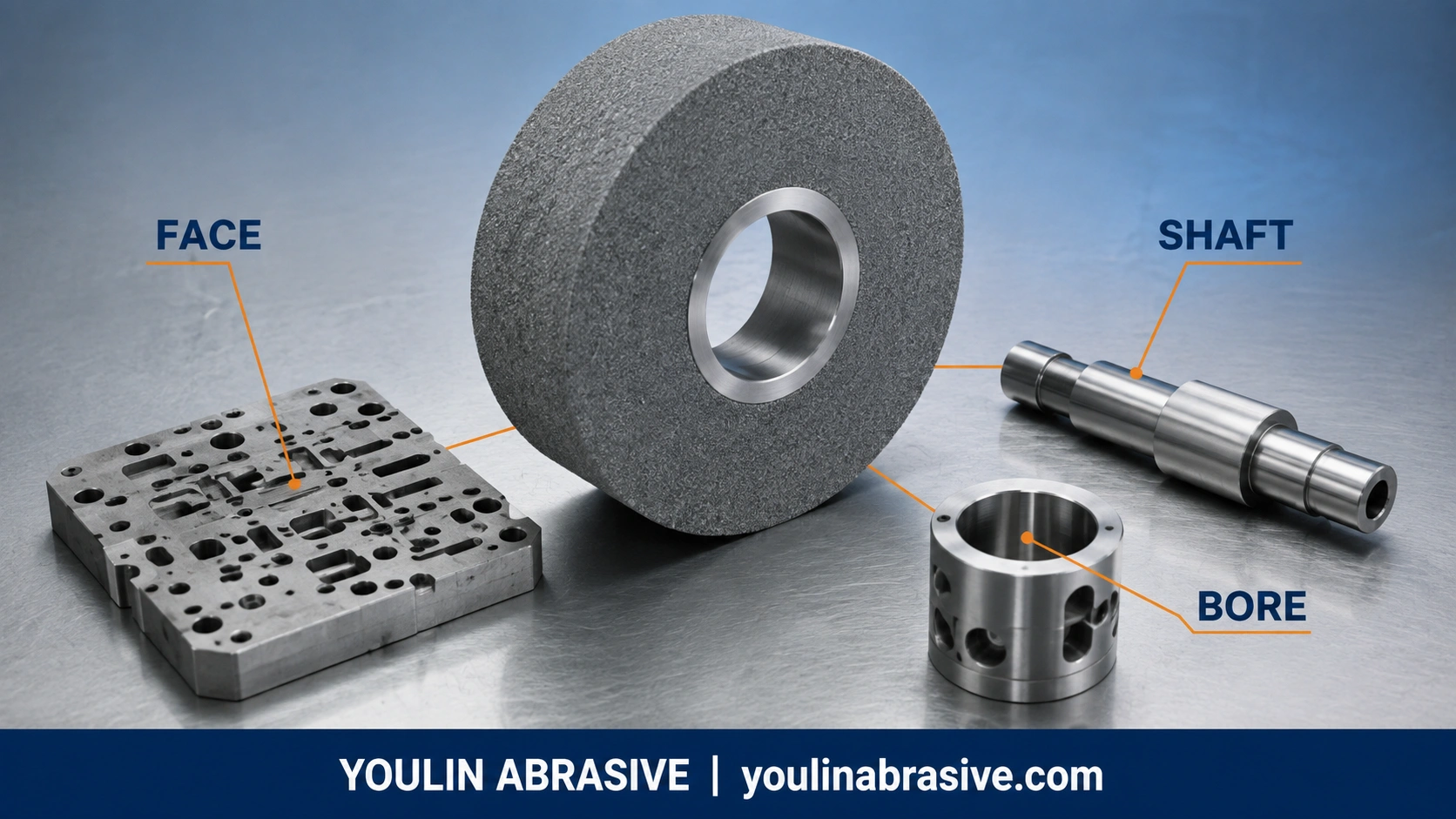
A valve plate face, a shaft and a bore create different grinding contacts. Review the ground material, process conditions and drawing requirements before requesting a wheel specification.

Identify the ground face, outside diameter or bore on the workpiece drawing
Connect material and hardness with contact area, coolant, dressing and machine condition
Record flatness, dimensions and surface finish as separate acceptance requirements
Send the current wheel details and evidence of the grinding problem

Overview

Quick answer

Grinding wheels for hydraulic component grinding should be reviewed against the actual material and hardness, surface or bore being ground, machine, wheel size and marking, coolant, dressing condition and current problem. A wheel name or matching diameter cannot establish suitability. Include the drawing requirements for flatness, dimensional consistency and surface finish, plus the way those results are measured.

This guide helps buyers prepare a hydraulic grinding application for review. Youlin supplies grinding wheels, abrasive tools and grinding wheel solutions only. Hydraulic components described here are customer workpieces and application contexts. Final wheel suitability may require technical review, sample confirmation or a controlled trial.

Start with the surface that needs grinding

  • A flat valve plate, an external shaft surface and an internal bore need different contact and access information.
  • Identify the layer being removed: base metal, hardened case or coating.
  • A smooth-looking surface does not confirm flatness, size or the specified roughness.
  • Describe when and where the problem appears before changing the abrasive or wheel grade.
Conceptual grinding wheel review map with flat-face, shaft and bore workpiece contexts
Conceptual application illustration: FACE, SHAFT and BORE identify different grinding surfaces. Confirm the real workpiece material, contact and drawing requirements for each operation.

Why hydraulic component grinding needs application review

The useful question is which surface must meet which drawing requirement, under which grinding conditions.

Separate geometry from surface texture

For a valve plate or pump face, record flatness and any parallelism requirement separately from roughness. For a shaft or valve spool, identify the diameter and any roundness or profile requirement. For a bore, show the inspection positions along its length. Use the customer's drawing and inspection method; there is no universal hydraulic tolerance to assume.

Describe the pattern across the grinding cycle

Report whether the first workpiece after dressing is acceptable, whether size or finish drifts later, and whether the issue occurs at one edge, a shoulder, a port or deep inside a bore. Mark these locations on a drawing or photo. This makes a request for precision grinding wheels for hydraulic components specific enough to investigate.
Common situations: surface, cylindrical and internal grinding

Surface grinding: valve plates and pump faces

For a surface grinding wheel for hydraulic components, identify peripheral or face grinding, the face width, stock allowance, fixture and any ports that interrupt contact. Compare the flatness measurement with the roughness result. Where distortion appears, include the workholding and thermal condition in the review instead of treating a finer grit as a flatness correction.

Cylindrical grinding: shafts, rods and valve spools

State whether the operation is traverse or plunge grinding and show the ground length, shoulders and work support. Identify coated and uncoated areas separately. Send the measured diameter trend and the location of chatter or finish changes; wheel profile, contact width and support may need different checks.

Internal grinding: bores and sleeves

For an internal grinding wheel for hydraulic components, send bore diameter, depth, entry clearance, wheel diameter and spindle or quill overhang. Internal contact and restricted access make coolant delivery, chip removal and rigidity important review points. Note whether the problem is near the entrance, at the far end or along the full bore.

Workpiece material and hardness: identify the layer being ground

Base metal and heat treatment

Give the actual steel, cast iron or other material grade where known, with hardness and its scale. State whether the workpiece is through-hardened, case-hardened or untreated, and whether stock removal stays within one layer. A component name such as valve body does not identify its grinding behavior.

Coatings need their own information

For a plated rod or coated sealing surface, identify the coating composition, thickness when known, substrate and which layers the wheel will contact. Do not transfer a recommendation for hardened steel directly to hard chrome, a carbide coating or another surface system. Flag uncertain material information for confirmation.

Workpiece hardness and wheel grade are different

Workpiece hardness describes the material being ground. Wheel grade describes the bond's retention of abrasive grains in a conventional wheel. A harder workpiece does not automatically call for a harder wheel grade; contact, stock, dressing and the required form also matter.

Wheel size, shape and existing specification

Confirm fit from dimensions

Send outside diameter, bore and thickness, with a drawing of recesses, profiles, working faces and mounting features where relevant. For an internal wheel, include the shank or mounting details and available clearance. Confirm the permitted operating speed and machine compatibility from the wheel and machine documentation.

Preserve the full wheel marking

Photograph and transcribe the complete existing specification, including abrasive, grit, grade, bond and structure where marked, plus concentration or abrasive-layer details when applicable. Mark unreadable characters as unknown. Photos help identify a wheel; measured dimensions, a drawing and application details are more reliable than visual similarity.

Coolant, dressing and machine condition

Check coolant at the grinding contact

Identify the grinding coolant, wet or dry operation, measured concentration if available, filtration and nozzle position. Describe access to a broad plate face or a deep bore and whether delivery changes during the stroke. The hydraulic fluid used by the finished assembly is not the grinding coolant specification.

Record what happens before and after dressing

Send the dressing method, dresser condition, settings, interval and reason for dressing. Describe how size, finish and wheel appearance change afterward. Dressing must suit the wheel construction; a single-layer electroplated wheel is not dressed in the same way as a dressable bonded wheel.

Include machine and workholding evidence

Record machine model, wheel and work speeds, feed, infeed and cycle stages. Include spindle or mounting concerns, wheel balance checks, work support and vibration observations. A wheel change alone cannot establish whether chatter or size drift originates in the wheel, the fixture or the machine.

Conventional, CBN, diamond or custom wheel: what may need comparison

These are review directions, not a finished specification for a hydraulic part.

Conventional grinding wheels

Aluminum oxide wheels are a common starting point for steel grinding. Conventional abrasive options should be compared with the actual material, contact, stock and dressing arrangement. An existing conventional wheel may remain suitable when its controlled process meets the drawing requirements.

CBN grinding wheels

CBN may be considered for hardened ferrous workpieces such as some valve spools or shafts. The material condition, bond, machine capability, coolant and dressing system still need review. Hydraulic component grinding wheels are not automatically CBN simply because the application requires dimensional consistency.

Diamond grinding wheels

Diamond may be considered for carbide, ceramic or other compatible non-ferrous material systems. It is generally not the starting choice for steel because of its chemical interaction with iron at grinding temperatures. Coated surfaces need a separate compatibility review that identifies the coating and any exposed substrate.

Custom wheel construction

Custom grinding wheels for hydraulic component applications may warrant review when bore access, mounting, a shoulder or a working profile limits a standard wheel. Provide the drawing and explain the limitation. Feasibility must be confirmed; customization does not mean every wheel design can be supplied.

Common mistakes when selecting a grinding wheel for hydraulic parts

Buying from size or appearance alone

An identical diameter can conceal a different abrasive, bond, grade or structure. Copy the current marking and connect it to the surface being ground.

Treating finish as the only acceptance criterion

A smooth plate may still fail flatness, and a smooth bore may still vary in size. List each drawing requirement with its measurement method; do not replace those requirements with a photograph of a reflective surface.

Changing several variables at once

Changing the wheel, coolant, dressing and feed together makes the result hard to interpret. Agree on a baseline and a controlled comparison, with the same material condition and inspection procedure. Record the result without assuming an improvement.

Evidence for the wheel review

Current grinding problem and possible review direction

The same visible symptom can have several causes. These prompts help organize evidence from hydraulic component grinding; they do not diagnose the process from a photo.

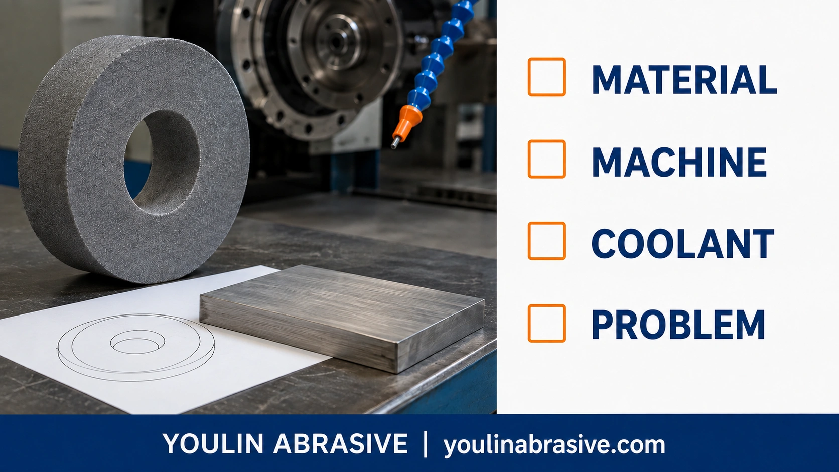
Conceptual inspection bench with a grinding wheel and material, machine, coolant and problem checklist
Conceptual checklist illustration: record material, machine, coolant and the current problem together, then add wheel dimensions, dressing records and inspection results.

Burn marks

Possible review direction
Review heat, wheel sharpness, coolant access and stock per pass.
Information needed
Mark the affected plate face, shaft area or bore location; send cycle and dressing records.

Wheel loading

Possible review direction
Review adhered material, chip clearance, abrasive compatibility and coolant condition.
Information needed
Send wheel-face photos, material or coating identity and the interval before buildup appears.

Wheel glazing

Possible review direction
Review dull grains, wheel grade and the condition left by dressing.
Information needed
Compare wheel appearance and grinding behavior before and after dressing.

Rapid wheel wear

Possible review direction
Separate grinding wear from dressing loss; review contact and form demand.
Information needed
Send measured wheel loss, dressing removal and the location of profile wear.

Chatter marks

Possible review direction
Review balance, runout, support and vibration before attributing the pattern to grit.
Information needed
Show mark spacing and location; include spindle, quill and workholding observations.

Unstable surface finish

Possible review direction
Review dressing consistency, coolant cleanliness and changing wheel condition.
Information needed
Send sequential roughness results, measurement method and the time since dressing.

Edge chipping or poor form holding

Possible review direction
Identify whether damage is on the workpiece edge or wheel profile; review support and local contact.
Information needed
Send close photos, the edge or profile drawing, material condition and where damage begins.

Frequent dressing

Possible review direction
Identify whether dressing is triggered by loading, glazing, finish drift or profile loss.
Information needed
Send the trigger, interval, dresser condition and what dressing actually restores.

Application factors to confirm

Use this reference to build one consistent application record. Mark unknown items clearly.

Workpiece material

What to confirm
Grade, heat treatment, coating and ground layer.
Why it matters
The contact material guides abrasive compatibility.
Review note
Do not infer material from the component name.

Workpiece hardness

What to confirm
Value, scale and location measured, if known.
Why it matters
Surface and core conditions may differ.
Review note
Identify whether grinding reaches another layer.

Grinding operation

What to confirm
Surface, cylindrical or internal; roughing or finishing.
Why it matters
Operation changes contact and wheel access.
Review note
Mark the grinding position on the drawing.

Contact area

What to confirm
Width, ground length and interrupted contact at ports or edges.
Why it matters
Local load and chip clearance can change.
Review note
Show where the problem is concentrated.

Wheel size

What to confirm
Outside diameter, bore, thickness and available clearance.
Why it matters
Fit and mounting must be confirmed.
Review note
Record measured values and speed markings.

Wheel shape/profile

What to confirm
Working face, recesses, shoulders and mounting features.
Why it matters
Geometry affects access and form transfer.
Review note
Use a dimensioned drawing for a special profile.

Existing wheel marking

What to confirm
Complete readable code and manufacturer reference.
Why it matters
It identifies the current comparison baseline.
Review note
Do not guess missing specification characters.

Coolant condition

What to confirm
Fluid, concentration when measured, filtration and delivery.
Why it matters
The grinding contact needs suitable coolant access.
Review note
Identify grinding fluid, not assembly hydraulic fluid.

Dressing condition

What to confirm
Method, dresser condition, settings and trigger.
Why it matters
Dressing changes the working surface and form.
Review note
Confirm the method suits the wheel construction.

Machine rigidity

What to confirm
Spindle, quill overhang, mounting, fixture and support.
Why it matters
Deflection or vibration may affect the result.
Review note
Include observations from the actual setup.

Current problem

What to confirm
Symptom, location and time within the cycle.
Why it matters
The pattern helps prioritize the checks.
Review note
Separate observations from suspected causes.

Finish or tolerance target

What to confirm
Drawing requirements and inspection method.
Why it matters
Roughness, flatness and size are different measures.
Review note
Send measured results as well as target values.
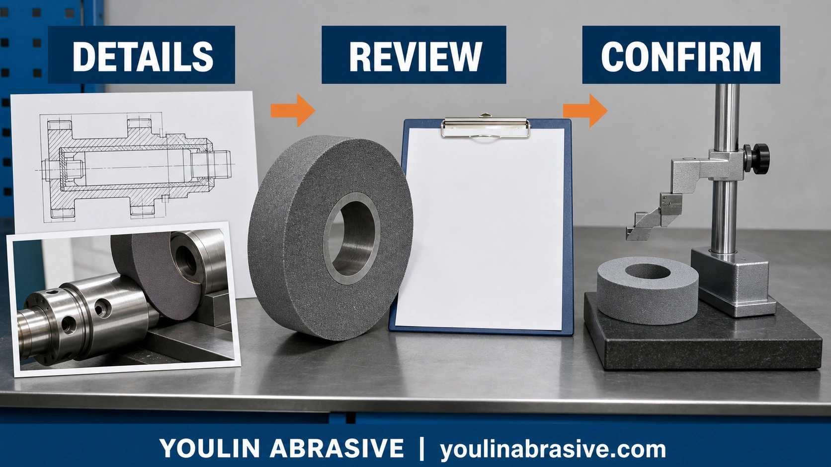
Conceptual hydraulic grinding inquiry workflow from application details through wheel review to confirmation
Conceptual inquiry workflow: DETAILS → REVIEW → CONFIRM. Confirmation may require additional information, a sample or a controlled trial; the illustration does not establish a finished wheel specification.

Buyer checklist

Check the application record before requesting a wheel

A complete record makes the next technical question easier to identify.

1

The drawing identifies the exact hydraulic workpiece surface and the layer being ground.

2

Wheel dimensions, mounting and the complete existing specification have been recorded.

3

Flatness, dimensions and finish each have a stated requirement and inspection method.

4

Coolant, dressing, machine condition and the problem history refer to the same grinding setup.

5

Unknown details are flagged, and any trial has agreed comparison conditions and acceptance criteria.

Application details

What buyers should send before inquiry

Send one application record for each materially different operation. A valve plate face and an internal bore should not share an unspecified wheel request.

  • Workpiece and material

    Component application, ground surface, material grade, hardness and coating or heat-treatment details

  • Wheel and drawing

    Measured wheel size, profile, mounting, full marking and dimensioned drawing where available

  • Photos

    Complete wheel, label, working face and problem area on the workpiece, with the location identified

  • Machine and process

    Model, surface/cylindrical/internal operation, contact area, stock, speeds, feed and infeed

  • Coolant and dressing

    Coolant delivery and condition; dressing method, settings, dresser condition and interval

  • Problem and inspection

    Burn, loading, glazing, wear, chatter or finish drift; current measurements and drawing targets

  • Trial and demand

    Sample or trial quantity, expected recurring demand and any unconfirmed information

Send your hydraulic component grinding application details, wheel size, photos, drawing and current grinding problem. We will review whether the information is enough for a grinding wheel recommendation.

Send Grinding Details →

FAQ

FAQ: hydraulic component grinding wheel review

Questions buyers often need to resolve before comparing specifications.

Can one wheel specification cover all hydraulic components?

Do not assume so. A plate face, shaft and bore can differ in material, contact, access and inspection requirements. Review each operation before carrying a specification across applications.

Does a hydraulic application automatically require CBN?

No. CBN may be reviewed for hardened ferrous workpieces, but conventional wheels may remain suitable. Diamond has other material contexts. Identify the ground material or coating and the complete process first.

What should I send for a flat valve plate?

Send the ground-face drawing, material and hardness, stock, workholding, contact at ports, wheel details and coolant/dressing records. Include flatness and roughness requirements with their measurement methods and current results.

What extra information is needed for an internal grinding wheel?

Include bore diameter and depth, entry clearance, wheel dimensions, mounting and quill overhang. Show where coolant reaches the contact and where size or finish changes along the bore.

Can a wheel recommendation be completed from one photo?

A photo can help identify appearance or a visible problem, but it cannot reliably establish dimensions, material condition or process settings. Send measured dimensions, a drawing, the current marking and application details.

Does an application review confirm final suitability?

An initial review may identify missing information or possible wheel directions. Final suitability may require technical review, sample confirmation or a controlled trial on the actual machine with agreed inspection criteria.